WIF-Pro Gasoline Applications Installation Manual
Water-In-Fuel Detection & Alert System
Phone: 888-646-6426
Website: WIF-Pro.com
Email: [email protected]
Thank You
Thank you for choosing the WIF-Pro Water & Fuel Monitoring System. We appreciate your trust in our products and are confident that WIF-Pro will provide reliable, long-term protection for your marine engine. Your satisfaction and your vessel’s safety are our top priorities.
Table of Contents
1. Step 1 – Installing the Control Box
2. Step 2 – Installing the Filter Parts
3. Step 3 – Installing the Sensor Ring(s)
4. Step 4 – Installing the Drain Bottle
5. Step 5 – Pulling the Communications Cable
6. Step 6 – Installing and Connecting the Power Cable
7. Step 7 – Testing the System
8. Three-Year Limited Manufacturer’s Warranty
9. Contact Information
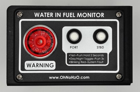
Step 1 – Installing the Control Box
There are two types of control boxes: a cut-in flush mount and a surface mount.
Flush Mount:
You will receive the control box with mounting screws and a cut-out template. Remove the screws and template to begin. Locate the mounting area on the boat and tape the template in place. Trace the cut-out, drill 3/8” corner holes, and use the provided abrasive jigsaw blade to cut. Always cut just outside the marked line so the hole is slightly larger. Test fit the box, adjust as needed, then drill centered pilot holes with the centering bit provided. Install screws while checking the box remains level. Ensure the gasket is installed on the back before mounting.
Surface Mount:
Determine location, hold box level, drill pilot holes through the side tabs, and mount with screws. Side tabs allow removal; the bottom center tab is the locking screw.
💡 Pro Tip: Apply blue painter’s tape around the cut line to protect the boat’s surface when cutting with the jigsaw.
[Photo – Flush Mount]
[Photo – Surface Mount]
Step 2 – Installing the Filter Parts
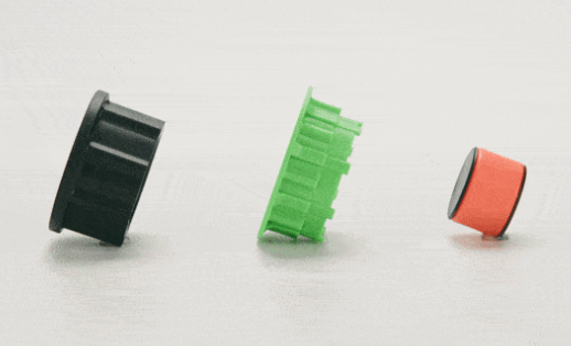
There are four filter-related parts: three installed inside the clear bowl and one spacer installed externally.
Internal:
1. Drop the orange indicator into the center tube.
2. Install the green float around the tube, flange facing up.
3. Install the black stopper flush with the top of the tube (flange facing up). Do not push further.
External:
4. Install the spacer between filter base and mounting surface. Use longer screws if needed.
ℹ️ Note: The black stopper has a light siliconized grease coating on the inside surface to assist proper installation. Do not remove this grease.
💡 Pro Tip: Apply a light layer of siliconized grease to the O-ring of the clear bowl before reinstalling. This makes future removal easier.
[Photo – Internal Filter Parts]
[Photo – Spacer]
Step 3 – Installing the Sensor Ring(s)
1. Pull out the locking latch to unlock.
2. Firmly push the sensor ring straight up onto the filter until it clicks into place. A firm push will not cause damage.
3. Twist the ring to confirm it is seated in the groove. Once confirmed, close the latch.
4. Mount the Y bracket using the provided self-tapping screw. Align the screw height with the top of the filter base or spacer.
💡 Pro Tip: Align the Y bracket screw with the top of the filter base for best results.
ℹ️ Note: Do not over-tighten the mounting screw. Excessive torque can damage the bracket or filter housing.
[Photo – Sensor Ring]
[Photo – Y Bracket]
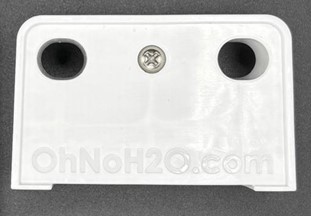
Step 4 – Installing the Drain Bottle
1. Mount the C-clip using the provided screws.
2. Snap the drain bottle into the clip at its neck. To remove, pull the bottom outward.
💡 Pro Tip: Mount the drain bottle near the filter for convenience during draining
[Photo – Drain Bottle]
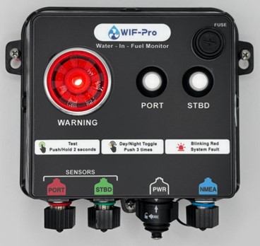
Step 5 – Pulling the Communications Cable
1. Use the attached pulling assembly to route the cable from the control box to the filter.
2. Both ends are female, so orientation does not matter.
3. After pulling, remove the tool and transfer the dust cap.
4. Connect the cable between the sensor ring M12 connector and control box. All connectors are color-coded.
ℹ️ Note: All cables and control box connectors are color-coded to ensure proper placement.
💡 Pro Tip: Snap male and female dust caps together to keep them clean for reuse.
[Photo – Cable Pulling]

[Photo – Connector]
Step 6 – Installing and Connecting the Power Cable
1. Connect power to an ignition-on source so WIF-Pro powers only when ignition is active.
2. Connect positive and ground wires using provided connectors (ring, fork, piggyback, or butt).
3. Seal connections with heat-shrink tubing.
4. Insert power connector into control box until it clicks. Twist before pulling to remove.
ℹ️ Note: Heat-shrink label on cable identifies positive and ground wires.
💡 Pro Tip: Use the small heat-shrink sleeves provided to bulk up thin wires for proper sealing in connectors.
[Photo – Power Source]
[Photo – Control Box Power Connection]

Step 7 – Testing the System
Initial Power-Up:
• Switch on power. The control box runs a 10-second start-up sequence.
• After start-up, all LED push-buttons display solid green indicating monitoring is active.
🔧 Troubleshooting: If any push-button LED flashes red, check cable connections at sensor ring and control box.
NMEA Connectivity:
• Locate the blue NMEA LED near the M12 connector.
• Solid blue = system connected.
• Flashing blue = searching but not detected; check drop cable connections from WIF-Pro to backbone.
• Off (no light) = no NMEA power; check drop cable connections from WIF-Pro to backbone.
Manual Sensor Test:
• Press and hold each LED button for 2 seconds.
• Alarm should sound and LED turns solid red.
Chart Plotter Confirmation:
• Alerts should display on MFD for each engine.
🔧 Troubleshooting: If no alerts appear but NMEA LED is solid blue, check alert settings on your MFD.
[Photo – Control Box LEDs]
[Photo – Chart Plotter]
Three-Year Limited Manufacturer’s Warranty
WIF-Pro warrants this product against defects in material and workmanship under normal use for three (3) years from purchase.
Exclusions:
- Improper installation or operation
- Normal wear and tear
- Damage due to accident, fire, flood, or nature
- Labor costs for removal or reinstallation
For warranty service, please contact WIF-Pro with proof of purchase.
Contact Information
OhNoH2O LLC / WIF-Pro
5458 1st Road
Lake Worth, Florida 33467
Phone: 888-646-6426 or 888-OhNoH2O
Website: WIF-Pro.com
Step 1 – Installing the Control Box
Overview:
There are two control box types: cut-in flush mount and surface mount. Each has its own procedure.
Cut-In Flush Mount Control Box
-
Remove the four corner mounting screws and the cut-out template from the box.
-
Select the mounting location (center console or under console recommended).
-
Use masking tape to affix the cut-out template in place.
-
Remove the perforated section from the template, then trace the cut-out area with a permanent marker.
-
Drill four corner holes (~3/8” diameter) to allow insertion of the jigsaw blade.
-
Use the provided abrasive carbide blade with a jigsaw to cut slightly outside the marked lines (this ensures the box will fit).
-
💡 Pro Tip: Before cutting, apply blue painter’s tape around the cut-out area to protect the boat’s surface from scratches caused by the jigsaw base.
-
-
Test-fit the control box and adjust the opening as needed.
-
Ensure the gasket is installed on the back of the box before mounting.
-
Using the provided centering drill bit, drill a centered pilot hole at one mounting tab.
-
Install one screw, re-check level, then drill the opposite corner pilot hole and install that screw.
-
Once level, drill the remaining two pilot holes and install screws.
Note: Using the centering drill bit ensures all pilot holes are perfectly aligned with the box’s mounting holes.
Surface Mount Control Box
-
Choose the mounting location.
-
Use the centering drill bit through the side mounting tabs to drill two pilot holes.
-
Install the two mounting screws while keeping the box level.
-
The side mounting tabs are sliding tabs — the box can be removed without fully removing these screws.
-
The bottom center tab uses a locking screw. Only this screw must be removed to take the box off.
✅ Mounting of the control box is now complete.
Step 2 – Installing the Filter Parts
Overview:
There are four filter-related parts: three are mounted internally inside the clear bowl, and one spacer is mounted externally behind the filter base.
Internal Filter Parts (Inside the Clear Bowl)
-
Orange Indicator – Drop the orange indicator into the center of the cylindrical tube in the clear bowl.
-
Green Float – Slide the green float over the cylindrical tube, allowing it to sit freely around the tube.
-
Black Stopper – Slide the black stopper onto the cylindrical tube the same way as the float, but push it down only until it is flush with the top of the tube.
-
⚠️ Important: Do not push the stopper further down than flush with the top.
-
Both the float and stopper have a flange — always install these with the flange facing upward.
-
ℹ️ Note: The black stopper has a very light layer of siliconized grease on the inside surface to assist with proper installation and seating. Do not remove this grease layer.
-
Once all three parts are installed, reinstall the clear bowl onto the bottom of the filter element.
💡 Pro Tip: Before reinstalling, apply a very light layer of siliconized grease to the O-ring on the clear bowl. This will assist with easier removal during future maintenance.
External Filter Part (Spacer)
-
Spacer – Install the spacer between the filter base and the surface the filter is mounted to.
-
If the filter is already mounted, remove the mounting screws, slide the spacer into place, and reinstall the screws.
-
If the original screws are too short, use the longer screws provided in the WIFPRO accessories box.
-
✅ With these four parts correctly installed, the filter assembly is complete.
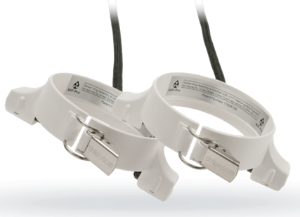
Step 3 – Installing the Sensor Ring(s)
Overview:
Each fuel filter will require a sensor ring. For multi-motor systems, install one sensor ring per filter.
Sensor Ring Installation
-
Ensure the locking latch on the front of the sensor ring is pulled outward (unlocked).
-
Firmly push the sensor ring straight up onto the filter until it clicks into place.
-
A firm push is recommended and will not cause damage to the sensor ring.
-
-
Once clipped in, rotate the sensor ring slightly around the filter to confirm it is properly seated in the groove.
-
If the ring spins smoothly while staying in the groove, it is correctly installed.
-
-
Close the front locking latch to secure the sensor ring in place.
Mounting the Sensor Y
-
Locate the mounting “Y” bracket and remove the provided self-tapping screw and cap.
-
Position the Y on either side of the filter (choose whichever side is more convenient for your installation).
-
Install the Y using the self-tapping screw.
-
💡 Pro Tip: For best results, mount the Y so the screw is aligned with the top of the filter base or the top of the spacer (they are effectively the same height).
-
ℹ️ Note: The mounting screw should be snug, but do not over-tighten. Excessive torque can damage the mount.
-
✅ With the “Y” bracket mounted the sensor ring installation is now complete.
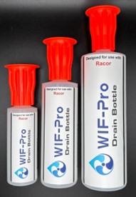
Step 4 – Installing the Drain Bottle
Overview:
The drain bottle collects contaminants or water drained from the filter. It is mounted with the provided C-clip and two self-tapping screws.
Installation
-
Select a mounting location for the drain bottle.
-
Recommendation: Mount it near the filter assembly so it is convenient to access when draining contaminants or water.
-
-
Secure the C-clip in place using the two self-tapping screws provided.
-
Snap the drain bottle into the C-clip by sliding the neck of the bottle (the skinnier portion) into the clip until it locks into place.
-
To remove the drain bottle, pull outward at the bottom of the bottle until it disengages from the C-clip.
💡 Pro Tip: Mount the drain bottle within easy reach of the filter to simplify maintenance and ensure quick access when draining water or contaminants.
✅ With the drain bottle securely installed, the filter system is ready for future maintenance operations.
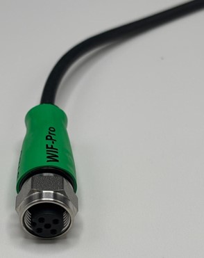
Step 5 – Pulling the Communications Cable
Overview:
The communications cable connects the sensor ring(s) to the control box. Each sensor ring assembly includes its own cable.
Installation
-
Use the cable end with the attached pulling tool assembly (provided) to pull the cable through the boat’s conduit or pulling tubes.
-
ℹ️ Note: Both ends of the cable are female connectors, so it does not matter which direction you pull the cable.
-
-
Route the cable from the control box location to the back of the boat near the filter assembly.
-
Once pulled, remove the custom pulling tool with its vinyl cap.
-
On the opposite end of the cable, remove the extra dust cap and place it on the end where the pulling tool was just removed. This ensures both ends remain protected.
-
Connect one end of the cable to the sensor ring M12 connector.
-
Connect the other end of the cable to the control box.
-
ℹ️ Note: All cables and control box connectors are color-coded and labeled to ensure proper connections in the correct locations.
-
💡 Pro Tip: After connecting the cable to the sensor ring, snap the two dust caps (male and female) together. This keeps the inside of the caps clean so they can be reused later without introducing debris into the communications cable pins or sockets. The same method can be used on the control box end.
✅ With the communications cable pulled and connected, the control box and sensor ring are now linked for operation.
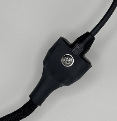
Step 6 – Installing and Connecting the Power Cable
Overview:
The WIFPRO control box requires a power connection for operation. Proper power sourcing ensures the system is active only when needed and protects against unnecessary battery drain.
Installation
-
Determine Power Source
-
💡 Pro Tip: It is highly recommended to connect the WIFPRO to an ignition-on power source so the system only runs when the motor ignition is on.
-
-
Make Power Connections
-
Connect the positive power wire from the WIFPRO cable assembly to your chosen power source.
-
Connect the negative wire (ground) to a proper grounding point.
-
ℹ️ Note: A heat-shrink label is provided on the end of the power cable assembly identifying which wire is positive and which is negative/ground.
-
-
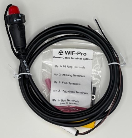
Use Proper Connectors
-
ℹ️ Note: The WIFPRO accessories box includes a variety of heat-shrink connectors to fit different installation needs:
-
#6 and #8 ring terminals
-
Fork connectors
-
Piggyback connectors
-
Butt connectors (for extending the power cable if needed)
-
-
-
Seal Small Wire Ends
-
💡 Pro Tip: Use the small heat-shrink sleeves (provided in the accessories box) on the ends of the small wires. This increases the wire diameter slightly, allowing the heat-shrink connectors to seal properly and securely.
-
-
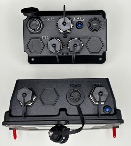
Connect to Control Box
-
Insert the power connector into the socket on the back of the control box.
-
The connector is a push-lock style: push it firmly until it clicks into place.
-
To remove the connector later, twist before pulling to disengage the lock.
-
✅ With the power cable connected, the WIFPRO system is now ready for final testing.
Step 7 – Testing the System
Overview:
Once installation is complete, the WIFPRO system must be powered up and tested to ensure correct operation and proper communication with your boat’s NMEA network (if applicable).
Initial Power-Up
-
Switch on power to the WIFPRO system.
-
The control box will begin a start-up sequence that takes approximately 10 seconds.
-
After the start-up sequence completes, all LED push-buttons on the control panel should display a solid green light, indicating that monitoring is active.
-
🔧 Troubleshooting Tip: If any push-button LED is flashing red, check the communications cable connections at both the sensor ring and the back of the control box for the corresponding filter.
-
NMEA Connectivity Check
-
Locate the blue NMEA indicator LED on your control box, positioned next to the M12 NMEA connector.
-
The NMEA LED should display a solid blue light, which confirms the WIFPRO system is actively connected to the NMEA network.
-
🔧 Troubleshooting Tip 1: If the NMEA indicator LED is flashing blue, the WIFPRO system is searching but has not detected the NMEA network. Check the NMEA drop cable connections from WIFPRO to the backbone.
-
🔧 Troubleshooting Tip 2: If the NMEA indicator LED is off (no light at all), the WIFPRO system is not detecting NMEA power. Verify the drop cable connections from WIFPRO to the backbone.
-
Manual Sensor Test
-
To verify each filter sensor operation, press and hold its corresponding LED push-button for 2 seconds.
-
A correct test result will:
-
Trigger the system alarm.
-
Change the pressed button’s LED from green to solid red.
-
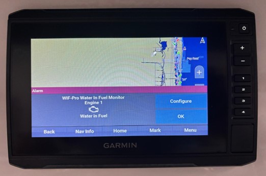
Chart Plotter Confirmation (NMEA Systems Only)
-
During manual sensor testing, each activated test should also trigger a visual alert on your chart plotter, corresponding to the specific engine being tested.
-
🔧 Troubleshooting Tip: If you are not receiving alerts on your chart plotter or MFD and the blue NMEA LED is solid blue, check the alert settings on your chart plotter/MFD to confirm that all alert functions are enabled.
-
✅ Done installing WIF-Pro.
